Komli

Monday, June 30, 2008

Robot tat acts like Rat


ScienceDaily (Feb. 21, 2005) — Robots that act like rat pups can tell us something about the behavior of both, according to UC Davis researchers.

This robot was designed with the same basic senses and motor skills as a rat pup. (Sanjay Joshi/UC Davis photo).

Bug Robot

Mechanical Engineers Have New Bug-Inspired Robot That Senses Its Way With Flexible Antenna.


July 1, 2005 — Researchers have developed a flexible, sensor-laden artificial antenna to help a robotic "bug" move and navigate just like the common cockroach. The bug can curry along walls, turn corners, avoid obstacles, and feel its way through the dark. In rescue operations, such robots could be sent to explore collapsed buildings and other situations that could pose hazards or just be inaccessible to humans.

HOW IT WORKS: Most robotic vehicles designed to navigate dangerous terrain rely on artificial vision or sonar systems to find the safest path. But robotic "eyes" don't operate well in low light and sonar can be confused by polished surfaces. The Johns Hopkins University scientists have turned to touch, inspired by how bugs use this sense to navigate dark rooms with varied surfaces. Just like a cockroach's antenna, the artificial version sends signals to the electronic brain of a wheeled robot, enabling the machine to scurry along walls, turn corners, and avoid obstacles in its path.

The antenna is made of cast urethane, a flexible substance that resembles rubber, encased in a clear plastic sheath. It contains six strain gauges, sensors that change resistance as they are bent. The device has been calibrated so that certain electric voltages correspond to certain bending angles as the antenna touches the wall or some other object. This data is fed to the robot's controller, enabling it to sense its position in relation to the way and to maneuver around obstacles. For instance, when the antenna signals that the robot is moving too close to a wall, the controller steers it away.

WHAT IS SWARM INTELLIGENCE: Building "swarms," of robotic insects that work together to adapt to their environment is part of "evolutionary robotics": creating machines that are digitally "bred" to evolve themselves. Swarm intelligence is the notion that complex behavior can arise from large numbers of individual agents each following very simple rules. For example, ants follow the strongest pheronome trail left by other ants to find the most efficient route to a food source, through a process of trial and error. A chunk of the plot in Michael Crichton's novel Prey was inspired in part by an experiment in which a fleet of robotic predators were programmed to seek out "prey" to get their next energy boost. The mechanical "prey," in contrast, were programmed to "graze" on special light sources and to keep alert for potential predators. The respective robots evolved increasingly complex hunting and escape strategies as the swarms of robots accumulated more and more data (in the form of experience) on which to base their decisions.

sciencedaily.com for more info.

Grass Hopper Inspired robot


About the size of a locust and weighing on 7 grams, this tiny robot can jump 27 times its own size.

Grasshopper-Inspired Jumping Microrobot Can Make Staggering Leaps

ScienceDaily (May 22, 2008) — Researchers from the Laboratory of Intelligent Systems at EPFL are unveiling a novel, grasshopper-inspired jumping robot at the IEEE International Conference on Robotics and Automation May 21 in Pasadena, California. The robot weighs a miniscule 7 grams, and can jump 1.4 meters, or more than 27 times its body size -- ten times farther for its size and weight than any existing jumping robot

Wall climber (Robotics News)


Researchers have designed a robot that uses a novel form of electrically activated adhesion to enable it to scale any kind of vertical surface. The robot can even climb surfaces that are dusty or wet, be they concrete, glass, or drywall.

"What's really unique about this is the technology, not the robot," says Harsha Prahlad, senior mechanical engineer at SRI International, a nonprofit research organization based in Menlo Park, CA. There are other robots that can climb walls. But these have usually involved using microscopic fibers designed to mimic the function of the hairlike setae that give geckos their remarkable sticking power, Prahlad says.

In contrast, SRI's robot works by inducing electrostatic charges in the surface of a wall. The advantage here is that the adhesive climbing surfaces of the robot can be turned off, making movement much simpler, says Prahlad. It also makes the robot's adhesive surfaces self-cleaning, he says, thereby avoiding any gradual buildup of dust and dirt that would ultimately reduce the adhesion.

Tests have shown that the robot is capable of generating 1.5 newtons of sticking force per centimeter square of contact with a wall. Presenting his results at this year's International Conference on Robotics and Automation, in Pasadena, CA, Prahlad showed that the robot was able to scale walls while carrying weights of up to 75 pounds.

"It's an interesting and robust approach," says Metin Sitti, a mechanical engineer at Carnegie Mellon University, in Pittsburgh, who has been working on wall-climbing robots for some time. However, he says, the forces generated are just one-tenth as strong as is currently being seen when the gecko-inspired approach is used.

On the plus side, however, the simplicity of Prahlad's approach should make it easier to apply to human wall-climbing applications, says Nicola Pugno, a professor of structural mechanics at Turin Polytechnique, in Italy, who has been working on a sort of Spiderman suit using nanotube-covered adhesive surfaces.

"There is no fundamental reason why you can't scale this up to, say, 200 pounds," says Prahlad. So with a suitable interface, it should be possible to allow a human to use this technology to climb walls, he says. However, such a system would require large pads to increase the surface contact of a person's hands. Otherwise, there would not be enough sticking power to support his or her weight, says Prahlad.

The attractive forces that create the adhesion come from electric fields generated by positive and negative electrodes within the surface pads of the robot, says Prahlad. When a high voltage is applied to these electrodes, positive and negative charges build up, which, in turn, attracts opposite charges from the surface of a wall near the electrodes

Sunday, June 29, 2008

Simple line follower using logic gates


This is a simple line follower using two sensors and without a microcontroller. We use here two types of logic gates and Lm 324 for the sensors. Two "OR" logic gates and one "Ex-OR" logic gates.The relay is used to run motors , can be replaced with motor driver L293D .

The ckt is self xplanatory , if u want to know the logic of its wrkng r have problem in understanding , wat its logic is , ask me and I will help you.

Wednesday, June 18, 2008

IR sensors From Scratch + Line follower


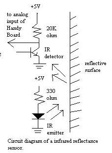
IR emitter and IR phototransistor
An infrared emitter is an LED made from gallium arsenide, which emits near-infrared energy at about 880nm.
The infrared phototransistor acts as a transistor with the base voltage determined by the amount of light hitting the transistor.
Hence it acts as a variable current source. Greater amount of IR light cause greater currents to flow through the collector-emitter leads.
As shown in the diagram below, the phototransistor is wired in a similar configuration to the voltage divider.
The variable current traveling through the resistor causes a voltage drop in the pull-up resistor.
This voltage is measured as the output of the device


IR reflectance sensors contain a matched infrared transmitter and infrared receiver pair.
These devices work by measuring the amount of light that is reflected into the receiver.
Because the receiver also responds to ambient light, the device works best when well shielded from abient light,
and when the distance between the sensor and the reflective surface is small(less than 5mm).
IR reflectance sensors are often used to detect white and black surfaces. White surfaces generally reflect well,
while black surfaces reflect poorly. One of such applications is the line follower of a robot.


Schematic Diagram for a Single Pair of Infrared Transmitter and Receiver


To get a good voltage swing , the value of R1 must be carefully chosen. If Rsensor = a when no light falls on it and Rsensor = b when light falls on it. The difference in the two potentials is:

Vcc * { a/(a+R1) - b/(b+R1) }
Relative voltage swing = Actual Voltage Swing / Vcc
= Vcc * { a/(a+R1) - b/(b+R1) } / Vcc
= a/(a+R1) - b/(b+R1)

The resistance of the sensor decreases when IR light falls on it. A good sensor will have near zero resistance
in presence of light and a very large resistance in absence of light. We have used this property of the sensor to form a potential divider. The potential at point ‘2’ is Rsensor / (Rsensor + R1). Again, a good sensor circuit should give maximum change in potential at point ‘2’ for no-light and bright-light conditions. This is especially important if you plan to use an ADC in place of the comparator

To get a good voltage swing , the value of R1 must be carefully chosen. If Rsensor = a when no light falls on it and Rsensor = b when light falls on it. The difference in the two potentials is:
Vcc * { a/(a+R1) - b/(b+R1) }

Relative voltage swing = Actual Voltage Swing / Vcc
= Vcc * { a/(a+R1) - b/(b+R1) } / Vcc
= a/(a+R1) - b/(b+R1)


If the emitter and detector (aka phototransistor) are not blocked, then the output on pin 2 of the 74LS14 will be high (apx. 5 Volts).
When they are blocked, then the output will be low (apx. 0 Volts). The 74LS14 is a Schmitt triggered hex inverter.
A Schmitt trigger is a signal conditioner. It ensures that above a threshold value, we will always get "clean" HIGH and LOW signals.
Not Blocked Case: Pin 2 High Current from Vcc flows through the detector. The current continues to flow through the base of Q2.
Current from Vcc also flows through R2, and Q2's Drain and Emitter to ground.
As a result of this current path, there will be no current flowing through Q1's base.
The signal at U1's pin 1 will be low, and so pin 2 will be high. Blocked Case: Pin 2 Low Current "stops" at the detector.
Q2's base is not turned on. The current is re-routed passing through R2 and into the base of Q1.
This allows current to flow from Q1's detector and exiting out Q1's emitter. Pin 1 is thus high and pin 2 will be low.
To detect a line to be followed, we are using two or more number of poto-reflectors.
Its output current that proportional to reflection rate of the floor is converted to voltage with a resister and tested it if the line is detected or not.
However the threshold voltage cannot be fixed to any level because optical current by ambent light is added to the output current.
Most photo-detecting modules are using modurated light to avoid interference by the ambient light.
The detected signal is filtered with a band pass filter and disused signals are filtered out.
Therefore only the modurated signal from the light emitter can be detected.
Of course the detector must not be saturated by ambient light, this is effective when the detector is working in linear region.


The line position is compeared to the center value to be tracked, the position error is processed with Proportional/Integral/Diffence filters
to generate steering command. The line folloing robot tracks the line in PID control that the most popular argolithm for servo control.
The proportional term is the commom process in the servo system. It is only a gain amplifire without time dependent process.
The differencial term is applied in order to improve the responce to disturbance, and it also compensate phase lag at the controled object.
The D term will be required in most case to stabilize tracking motion. The I term that boosts DC gain is applied in order to remove left offset error,
however, it often decrease servo stability due to its phase lag.
When any line sensing error has occured for a time due to getting out of line or end of line, the motors are stopped and
the microcontroller enters sleep state of zero power consumption.
Typical Examples of infrared Transmitter and Receiver installation


Tuesday, June 17, 2008

Maze Solver n Wall Follower .

A simple wall follower has to navigate easily following the wall , that is when evr there is a turn (perfect 90 degree as by the wall) the bot shuld also take a turn . Take a look at this picture .


First question which comes to your mind is how many sensors do one wuld need ?? . Wuld we need a micrcontroller .

Well we can make this by using only two sensors , and there is no need of a micrcontroller also.

CONDITIONS TO BE SET UP:

We wuld be using 2 sensors one at the rite and the other at the center .

(Left sensor- high ----------and center sensor- high

move fwd)

(Left sensor-low ----------and center sensor-high

take left)

(Left sensor-high ----------and center sensor -low
take rite).

Use a K map with the above conditions and get the logic circuit .
Connect the sensors to the input of u r logic and H bridge at the output.
Use motors of 60rpm nt faster than tat .

If u want more help plz ask.

COLOUR SENSORS

All color sensors work on the basic principle that when light of some color falls on an object , if the object is of same color as of the led , then the object absorbs that color which means there is no reflection.

We would be making the ckt in the same way as we did for the IR led detector ckt , but we wuld be using LDR for our detection purpose , (IR cant be used as they catch only IR waves) , and in place of the IR transmitter we wuld be using three leds of red, blue and green.

WORKING:
Light up each of the leds one at a time , ie red , then blue n green , if the obstacles are of red blue and green colour then you wuld be getting different outputs ( REMEMBER VIBGYOR) .

With micrcontrollers , lit up the red led if there is reflection take the ADC reading
do the same for other leds and take thier ADC reading , we will know which colour its detecting.
One sensor wuld be lit up always .


Use a potentiometer with each of the LEDs to get a better reading , as there wuld be slight color difference .The circuit will be the same as for the ir sensor which i have explained in my previous post , with litlle changes .Hope u njyd it

Monday, June 16, 2008

BUMP SENSOR

So, you've fitted some motors to your robot and its happily driving around but it probably keeps colliding with obstacles and getting stuck. You need a way for your robot to detect collisions and move around objects. Enter the humble bump sensor:

A bump sensor is probably one of the easiest ways of letting your robot know it's collided with something. The simplest way to do this is to fix a micro switch to the front of your robot in a way so that when it collides the switch will get pushed in, making an electrical connection. Normally the switch will be held open by an internal spring.

Micro switches are easy to connect to micro controllers because they are either off or on, making them digital. All micro controllers are digital, so this is a match made in heaven. Micro switch 'bump' sensors are easily connected to the Robocore, simply plug them into any free digital socket and away you go.

The following diagram shows a typical circuit for a micro switch bump sensor. The resistor is important because it holds the signal line at ground while the switch is off. Without it the signal line is effectively 'floating' because there is nothing connected to it, and may cause unreliable readings as the processor tries to decide if the line is on or off.


If you dont get these microswitches u can make one easily , using a spring mechanism.

Friday, June 13, 2008

MORE E BOOKS

(1)

Robots Androids & Animatrons by John Iovine

download from here
Lovely book , gives u a good start for professional robotics.

What u can get from this book????

Movements and drive system.

DTMF controlled vehicle (tats using u r phone)

Making a walker

Speech Controlled bot

Under water bots

Aerobots

One necessary book , I double my money on this to read.

(2)

Robotics and Process Control Cookbook

download from
here


Not tat great to read on if u have other e books , but has gud examples of various things.

(3)

Build a Remote Controlled Robot

download from
here

Diff methods of making a remote controlled car , from Ir , Rf to various methods.

(4)

8051 microcontoller

download from here

One stop to start for micrcontrollers r download ayalas e book from my other post on e books.