Komli

Monday, March 31, 2008

4 WHEEL DRIVE PROBLEMS

Frictional losses in four wheeled differential drive configuration while turning:


Four wheel differential robots have one major problem which people often forget to take
care of while designing there robot. While robot takes turn with zero turning radius its
wheels skids. It reduces accuracy of motion and can damage both robot’s motors and
wheels.
Above figure shows foot print of Dexter 2 robot. Dexter 2 is 5 feet tall and weights
almost 125 Kg. Consider this robot wants to turn clockwise. Robot will move its left pair
of wheels forward and right pair of wheels backward.
• Dotted circle indicates path on which wheels will move it passes through
center point of wheels.
• Blue arrow indicates wheels instantaneous trajectory it is tangent to the
dotted circle passing through wheels center.
• Red arrow indicates wheels motion direction.
Observation: Notice that there is a small angle of 28.43 degrees between red arrow and
blue arrow. Here red arrow shows hat wheel is actually trying to move forward or
backward. But wheels are moving in circular direction i.e. they are literally skidding
along the circular direction.
That’s why in this robot base is designed as wide as possible and distance between the
front and back wheels is kept as small as possible without compromising stability of therobot. If distance between robot’s front and back wheel is further increased then this
angle will increase and will cause large frictional losses. If this angle is increased above
45 degrees it is very likely that robot will not be able to rotate with zero turning radius
because motors will not be able to overcome friction due to skidding.


DPDT WIRED SWITCH CONTROL


GIVE THE CONNECTIION FOR BOTH MOTORS AS SHOWN .

Sunday, March 30, 2008

FIRST MANUAL BOT

Here we will be making our first three wheel drive (a manual bot ) with this u can start making u r own manual bots after this easily

In three wheels differential drive configuration two wheels are connected to motors.
Third wheel is caster or omni directional wheel which allows motion in any direction.
Three wheeled configuration is often used in smaller size robots.
It offers two advantages:
1. All the wheels gets good contact
2. Problem of skidding while turning is avoided.
3. Robot can take turn by stopping one wheel and moving other wheel


MATERIALS USED


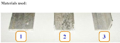
1. Flat Aluminum stripe: Width: 1 inch, Length 1 feet, thickness approx 1.5 mm or
above
2. Aluminum ‘C’ channel: Width: 1 inch, Length 1 feet, thickness approx 1mm or
above
3. Aluminum ‘L’ angle: Width: ¾ * ¾ inch, Length 5 feet, thickness approx 1mm or
above

FABRICATION OF MACHINES CHASSIS
Cut Aluminum ‘L’ angle of 14 cm length. ( and Aluminum ‘C’ channel of
16 cm length. (
Now fix Aluminum ‘L’ angle or ‘C’ channel firmly in the bench wise . Mark
Aluminum channel using tri square (. (this will make sure that cutting
guidelines at right angled to the angle / channel.)


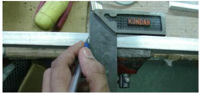
Cut Aluminum angle / channel with hexa blade.


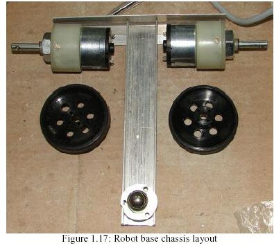
Now arrange the 14 cm ‘L’ angle and 16 cm ‘C’ channel in ‘T’ configuration as shown in
fig. 1.17. Drill holes with 3mm of 1/8 drill bit ( using drill machine on the
intersection of channel and angle.

Use 3mm nut and bolt: flat head, 10mm in length along with Spring washer
for 3mm or 1/8 inch nut and bolts for join the ‘L’ angle and ‘C’ channel.
Spring washer will prevent loosing of nuts and bolts in vibrations.
Always use spring washer between the nuts and bolts.
Be very careful while holding bolt with Pliers and tighten nut with screwdriver. If
screwdriver slips it can hurt other hand


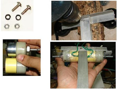
As shown in fig above DC geared motors gearbox’s diameter is slightly bigger than
diameter of motor. For better motor mounting gearbox and motor should have same
diameter. For increasing motor diameter of the motor foam tape is used(the thing in yellow).

Place the motor on the ‘L’ angle and tightly wrap tape around it. Do the same procedure
of the other motor. It is very important that motors back side touches ‘C’ channel. This
will be explained in fig later on.

Photo showing chassis after motor mounting is shown above .

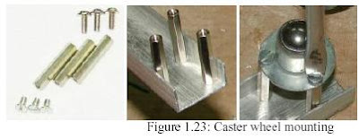
Now we will mount caster wheel at the front end of the chassis. First place caster wheel
on the Aluminum ‘C’ channel at the front side. Mark three holes on the ‘C’
channel. Drill holes with 3mm of 1/8 drill bit ( using drill machine. Mount 3
25 mm studs (fig below) using 3mm nut flat head nut (fig below). Mount caster wheel
on the studs using counter sink nuts (fig below).


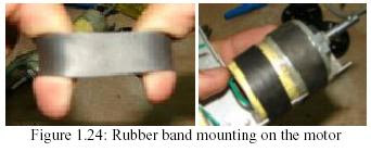
Take old piece of tire tube (fig 1.24) and cut approximately 11mm band. Stretch the
rubber band to remove its stiffness. Now mount two such bands on the motor. This will
make motor mounting firm.


Mount wheels (fig 1.13) on the two motor shafts.


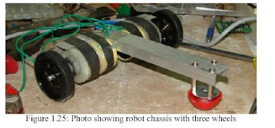
Now u can mount the batteries on the chassis by making a small box either of aluminium r the some other material and fix it on to the chassis

NEXT TAKE A TEN WIRE STRIP AND GIVE THE CONNECTIONS TO THE DPDT SWITCH AS TOLD IN EARLIER POST .

THERE IT IS FINALLY U R FIRST MANUAL CONTROL BOT

FOR DIFFERENT EVENTS U CAN KEEP CHANGING THE CHASSIS AS THIS WAS BUILT KEEPING IN MIND OF LOW WEIGHT WE DID THIS THING U CAN ALSO WOOD (I PREFER XAM PAD AS MY CHASSIS) AS U R CHASSIS ALSO REST OF IT I WILL TELL U IN MY NEXT POST.


Saturday, March 29, 2008

MANUAL CONTROL TO DC MOTORS


WITH THIS THING WE WILL COME TO THE END OF MANUAL CONTROL THE SWITCH TAT I HAVE SHOWN OVER HERE IS ONLY FOR ONE MOTOR AND U NEED TO DO THE SAME FOR ANOTHER MOTOR AND THEN U CAN USE THE DIFFERENTIAL DRIVE SYSTEM TO RUN U R BOT

PIVOT DRIVE PRINCI


lThe most unique type of Locomotion system
lIt is composed of a four wheeled chassis and a platform that can be raised or lowered

lThe wheels are driven by a motor for translation motion in a straight line
lFor rotation one motor is needed to lower/raise the platform & another to rotate the chassis around the platform
lThis system can guarantee perfect straight line motion as well as accurate in – place turns to a desired heading


lThe system is quite complex in design
lA still more complex design uses only two motors. The wheels and the platform rotation are coupled to a single motor. When in translation the platform has no effect as it is above ground. And when turning, the wheels are off the ground due to the lowered platform
lThe machine is restricted to only in – place turns. This may be an hindrance in some cases

SYNCHRONOUS DRIVE SYSTEM


lAs the name suggests, it uses synchronous rotation of its wheels to achieve motion & turns
lIt is made up of a system of motors. One set of which drive the wheels and the other set turns the wheels in a synchronous fashion
l The two sets can be directly mechanically coupled as they always move in the same direction with same speed


lThe use of separate motors for translation and wheel turning guarantees straight line motion without the need for dynamic feedback control
lThis system is somewhat complex in designing but further use is much simpler

ARTICULATED DRIVE SYSTEM


lIn this mechanism the machine chassis (body) is deformed to achieve rotation in contrast to the steering wheels in car type drive


lTwo actuators (motors) are needed. One to drive the wheels and the other to change the pivot angle
lThis system shares most of it’s features with the car type mechanism
lThis is too an example of Non – Holonomic System

SKID STEER DRIVE


l
lA close relative of the differential drive system
lIt is mostly used in tracked machines e.g. tanks. Also finds application in some four / six wheeled robots
lThe left and right wheels are driven independently
lMultiple drive wheels on each side give increased traction. The effect is even greater for tracked machines
lSkidding causes the wheels to loose contact with the surface beneath and position tracking becomes difficult
lRest of it’s properties are more or less like the differential drive system

CAR TYPE DRIVE PRINCI


l
lThis is the car type drive and the most common in real world but not in robot world
lIt is characterized by a pair of driving wheels and a separate pair of steering wheels
lThe turning mechanism must be accurately controlled. A slight inaccuracy may cause large odometry errors
lThe system is Non – Holonomic hence path planning is extremely difficult as well as inaccurate
lThere are no direct directional actuators

DIFFERENTIAL DRIVE PRINICPLE


This is the most commonly used form of locomotion system used in mobile robots as it’s the simplest and easiest to implement
It has a free moving wheel in the front accompanied with a left and right wheel.The two wheels are separately powered
When the wheels move in the same direction the machine moves in that direction. Turning is achieved by making the wheels oppose each other’s motion, thus generating a


In-place (zero turning radius) rotation is done by turning the drive wheels at the same rate in the opposite direction
Arbitrary motion paths can be implemented by dynamically modifying the angular velocity and/or direction of the drive wheels
Total of two motors are required, both of them are responsible for translation and rotational motion


Differential Drive An Analysis

Simplicity and ease of use makes it the most preferred system by beginners
Independent drives makes it difficult for straight line motion. The differences in motors and frictional profile of the two wheels cause them to move with slight turning effect
The above drawback must be countered with appropriate feedback system. Suitable for human controlled remote robots

DIFFERENT LOCOMOTION PRINCIPLES

Differential drive
Car type drive
Skid steer drive
Articulated drive
Synchronous drive
Pivot drive
Dual differential drive

DC MOTORS

This kind of motors come in different ratings and these are mostly used by beginners bcoz the ease with which u can control them , these can rotate in both direction when the power supply is interchanged

when u give + of power supply to one terminal the motor and - ve of power supply to other terminal of the motor the motor wuld rotate in one direction, when u revrse the terminals of power supply the motors rotate in different direction.

Generally this motor comes with a speed of 2400 1200 rpm which are used in taperecorders but then this wuld not give enough torque so we use gears to get speed varyinf from 10 rpm to 1000 rpm (as speed increases torque desrceses) .

I l talk more abt stepper motors once i start of with elcectronics parts

WHAT DO U GET FROM THIS BLOG

Welcome to the site of robotics

I l be teaching u over here about robotics so tat u can start participating in the fest with an ease . I will try to put as much of the knowledge i have over here n we will also keep discusiing over different fests .