Komli

Saturday, May 17, 2008

BIOMETRIC ROBOT JOURNALS

This another list on robotic journals on biometric , can be used for paper presentation in engineering .Taken from societyofrobots.com one wonderfull site.

Adaptive Dynamic Walking of a Quadruped Robot on Irregular Terrain Based on Biological Concepts

Biomimetic Robot Navigation

Biomimetics: New Tools for an Old Myth

A New Hybrid Approach to Dynamic Modeling and Control Design for a Pectoral Fin Propelled UUV

Design of a Biomimetic Controlled-Curvature Robotic Pectoral Fin

A Novel Water Running Robot Inspired by Basilisk Lizards

Review of Fish Swimming Modes

Trends in Biorobotic Autonomous Undersea Vehicles (4.7mb)

Walking Robots and the Central and Peripheral Control of Locomotion in Insects

ARTIFICIAL INTELLIGENCE - ROBOTICS JOURNALS

Here is a list of journals , papers that engineering students can use for paper presentations , but shld have great fundas .

Cognitive Architecture, Concepts, and Introspection: An Information-Theoretic Solution to the Problem of Phenomenal Consciousness

CoSy: Cognitive Systems for Cognitive Assistants

Emerging Consciousness as a Result of Complex-Dynamical Interaction Process

Levels of Consciousness and Self-Awareness: A Comparison and Integration of Various Views

Single-Neuron Theory of Consciousness

Reinforcement Learning: A Survey

DC MOTOR BRAKING

We will discuss different ways of braking in the robots , there are 3 different ways as usual which goes from mechanical to electrical .This is basically needed when u want to go down the slope r up the slope, though these are not tat great braking as comapred to the real vehicles but of much help to us.

Mechanical Method :
The mechanical method is what is used on cars today. Basically you need something with very high friction and wear resistance, and then push it as strongly as possible to your wheel or axle. A servo brake works well.People think of using door stoppers but they are not of much help , I tried it n they just wasted my money and time .
Controls Method :
This method requires an encoder placed onto a rotating part of your DC motor. You will have to write an algorithm that determines the current velocity of your motor, and sends a reverse command to your H-bridge until the final velocity equals zero. This method can let your robot balance motionless on a steep hill just by applying a reverse current to your motors.

Electronic Method :
This method is probably the least reliable, but the easiest to implement. The basic concept of this is that if you short the power and ground leads of your motor( connect both the +ve leads of the battery to the two terminals of the motor), the inductance created by your motor in one direction will power your motor in the opposite direction. Although your motor will still rotate, it will greatly resist the rotation. No controls or sensors or any circuits overheating. The disadvantage is that the effect of braking is determined by the motor you are using. Some motors brake better than others.


So how do you short the leads when it is on a robot? Simple. Connect a MOSFET (transistor) and a relay as shown. The MOSFET turns on the relay, which creates a short between the motor leads. Turn the MOSFET on (set C high) with your microcontroller when you want to brake. Basically your motor will still have an H-bridge for normal control, but when you brake you turn the H-bridge off and use the braking circuit. And don't forget the heatsink and flyback diode! Important, or your circuit will melt/blow up.

SENSORS WITH TSOP CKT


This is a simple yet effective IR proximity sensor built around the TSOP 1738 module. The TSOP module is commonly found at the receiving end of an IR remote control system; e.g., in TVs, CD players etc. These modules require the incoming data to be modulated at a particular frequency and would ignore any other IR signals. It is also immune to ambient IR light, so one can easily use these sensors outdoors or under heavily lit conditions.
Such modules are available for different carrier frequencies from 32 kHz to 42 kHz.They cost some thing around 20Rs.
In this particular proximity sensor, we will be generating a constant stream of square wave signal using IC555 centered at 38 kHz and would use it to drive an IR led. So whenever this signal bounces off the obstacles, the receiver would detect it and change its output. Since the TSOP 1738 module works in the active-low configuration, its output would normally remain high and would go low when it detects the signal (the obstacle).

In the reciving part instead of using IC555 u can use the time from u r muc.

A part of the Source Code for the Previous LFR

The 8 sensors are connected the port 0 .The numbers 160 n 255 are a constant

which u take this has been explained un my previous post so jst take a look.


while (1){

#ifdef debug
if(rep<255) prev="PINA;" i="0;i<8;i++)">>i)&0x01);
rep=0;
}
#endif

if(PINA!=255){
rotpow=255;
ldev=rdev=0;

if(PINA.3==0)
rdev=1;
if(PINA.2==0)
rdev=2;
if(PINA.1==0)
rdev=3;
if(PINA.0==0)
rdev=4;

if(PINA.4==0)
ldev=1;
if(PINA.5==0)
ldev=2;
if(PINA.6==0)
ldev=3;
if(PINA.7==0)
ldev=4;

if(rdev>ldev)
move(R,0,195+12*rdev);
if(rdev<160) rotpow="160;}">HMAX)
{move(CW,0,rotpow);}
else
{move(CCW,0,rotpow);}
}
};
}

void move (unsigned char dir,unsigned char delay,unsigned char power) {
PORTC=dir;
if(dir==L || dir==R) {
hcount=(hcount+1)%MAX;
history[hcount]=dir;
}
LSPEED=RSPEED=255;//power;
//delay_ms(delay);
}

This is taken from priyank patels LFR code .

Friday, May 16, 2008

AVR LINE FOLLOWER PD CONTROL


The robot uses IR sensors to sense the line, an array of 8 IR LEDs (Tx) and sensors (Rx), facing the ground has been used in this setup. The output of the sensors is an analog signal which depends on the amount of light reflected back, this analog signal is given to the comparator to produce 0s and 1s which are then fed to the µC.

Starting from the center, the sensors on the left are named L1, L2, L3, L4 and those on the right are named R1, R2, R3, R4.

Let us assume that when a sensor is on the line it reads 0 and when it is off the line it reads 1.
The µC decides the next move so as to position the robot such that L1 and R1 both read 0 and the rest read 1.


Algorithm:

1. L= leftmost sensor which reads 0; R= rightmost sensor which reads 0.

If no sensor on Left (or Right) is 0 then L (or R) equals 0;

For example


2. If all sensors read 1 go to step 3,

else,

If L>R Move Left

If L

If L=R Move Forward

Go to step 4

3. Move Clockwise if line was last seen on Right

Move Counter Clockwise if line was last seen on Left

Repeat step 3 till line is found.

4. Go to step 1.


For a good voltage swing from the potential divider use

R1= Sqrt (Resistance of sensor when light falls on it * Resistance of sensor when light does not fall on it)


The 8 sensors are connected to PORTA.

You need not connect anything to AVCC and AREF, it is required only if ADC is used.

The L298 Motor Driver has 4 inputs to control the motion of the motors and two enable inputs which are used for switching the motors on and off. To control the speed of the motors a PWM waveform with variable duty cycle is applied to the enable pins. Rapidly switching the voltage between Vs and GND gives an effective voltage between Vs and GND whose value depends on the duty cycle of PWM. 100% duty cycle corresponds to voltage equal to Vs, 50 % corresponds to 0.5Vs and so on. The 1N4004 diodes are used to prevent back EMF of the motors from disturbing the remaining circuit.

Thursday, May 15, 2008

line follower with software diff

A simple line follower not following a curve can make a large diff jst by changing the software tats u r programme . Its always better tpo use more sensors than just a couple of them , use arnd 8 sensors rather than 4 r 6 . Now wat diff can a change in algo make , u can use PWM and PID control to make it more perfect bot .Even a Closed loop control system formed with the above two can be used.

PID CONTROL :
A proportional integral derivative controller (PID controller) is a common method of controlling robots. PID theory will help you design a better control equation for your robot.
Shown here is the basic closed-loop (a complete cycle) control diagram:


The point of a control system is to get your robot actuators (or anything really) to do what you want without . . . ummmm . . . going out of control. The sensor (usually an encoder on the actuator) will determine what is changing, the program you write defines what the final result should be, and the actuator actually makes the change. Another sensor could sense the environment, giving the robot a higher-level sense of where to go.

To get you started, here are a few terms you will need to know:

error - The error is the amount at which your device isnt doing something right. For example, if your robot is going 3mph but you want it to go 2mph, the error is 3mph-2mph = 1mph. Or suppose your robot is located at x=5 but you want it at x=7, then the error is 2. A control system cannot do anything if there is no error - think about it, if your robot is doing what you want, it wouldnt need control!

proportional (P) - The proportional term is typically the error. This is usually the distance you want the robot to travel, or perhaps a temperature you want something to be at.

derivative (D) - The derivative term is the change in error made over a set time period (t). This is usually the velocity of your robot. So if your robot was at x=5 about one t ago, and is at x=7 now, then the derivative term is 7 - 5 = 2/t. If you are using a microcontroller, you can calculate the time with this timer tutorial.

integral (I) - The integral term is the rate of change in the error made over a set period of time (t). This is usually the acceleration of your robot. If your derivative term was 2/t a second ago, and it is 2/t now, your integral term is 2 - 2 = 0/t^2. Thats an acceleration error of zero . . .

tweak constant (gain) - Each term (P, I, D) will need to be tweaked in your code. There are many things about a robot that is very difficult to model mathematically (ground friction, motor inductance, center of mass, ducktape holding your robot together, etc.). So often times it is better to just build the robot, implement a control equation, then tweak the equation until it works properly. A tweak constant is just a guessed number that you multiple each term with. For example, Kd is the derivative constant. Idealy you want the tweak constant high enough that your settling time is minimal but low enough so that there is no overshoot.

One example of only P control can be seen here: taken from amol deshmukhs site ,


This is a small line following robot designed to follow a white line drawn on a black surface. The software can be changed to interchange the colours. The software still has lot's of room for improvement but works well. It constantly corrects wrong moves using feedback mechanism which forms a closed loop control system.


mechanical design It has two DC motors in wheelchair design. Direction of the robot is controlled by controlling speeds of the two motors. Lets say the speeds are
Right wheel : SpeedR
Left wheel : SpeedL
To control the speed of the motor controlled power is fed by PWM ( Pulse Width Modulation ) technique.


electronic design Processor AVR ATmega16 [ the ADC feature comes in handy to read output of sensors ]
Motor driver : L293D ( 2 )
Sensors : IR LED-photodiode pair ( 2 )( non-modulated )
Power supply : Li-Ion cells ( 2 ) 1700mAHr giving 8V regulated with voltage regulator.


control algorithm and software
Lets say the two sensor outputs, i.e. the intensity of reflected light sensed at the two sensor positions is
Sensor Left : SensL
Sensor Right : SensR

If Err is the error of sensors from mean position then it will be proportional to the difference between the two sensor readings
Err = K * ( SensR - SensL )
Where K is constant of proportionality

If Err is a +ve quantity then we must drive Left motor a bit faster than the right i.e. the speed of right motor must be increased a bit and speed of motor right be decreased a bit
SpeedL = CntrSpeed + Kp * Err
SpeedR = CntrSpeed - Kp * Err

This is called Proportional Control


Check for my next post on 8 sensors using PD control wth algo.

The above one is only P control n taken from this site

http://www.me.iitb.ac.in/~adeshmukh/linefollower.php


Tuesday, May 6, 2008

Making A Gripper Arm for Pick n Place comps

I will be discussing over here various methods to hold objects , this is mostly used in pick and place comps.

1)USING ONLY MOTORS N DIRECTLY GRIPPING THEM TO ARMS.
Basic idea is to hold the object and also leave the object.We can use two simple dc geared motors of lower rpm n directly fix it to the bars as shown below
We used two dc geared motors of 10 RPM at the points A and B , fixed to the arms using gears at the two dots shown above A n B

RESULT:Couldnt sustain the force required to lift for a long period of time, so we changed our plan.


2)USING NUT BOLT MECHANISM:

Thi
s has been taken frm another site robotics for u which u can c in the link list on the rite side on my blog


This thing is self xplanatory when the motor starts rotating the nut keeps moving inside ,and hence the one of the arms fixed to it keeps moving inside . It gives gud result but was pretty to tough to implement for us , we gave try at it but werent much happy wth wat we had done so had to think some thing else which can be much simple .

3)SIMPLE GRIPPER USING SINGLE MOTOR:
We
used some simple objects tat we could get hand on , so we used a a girder u can get this in any mechanical shop(he will charge pretty high if u tell u r purpose).This is how they luk like

The first pic is that of girders (which u can make them using aluminium and drilling holes in it)
and the second pic is that of our arm , we used a 10 rpm motor to pull the two strings.Use a spring in reverse of the strings to pull so tat it can even with draw objects when needed.This is how it goes finally


This is how it finally luks like dont use a high rpm motor thinking tat we can grip it fast , it will be out of control so be carefull of it , we could grip this to lift a 4.6kg objects which we tested in our colleges . This was all because we could use a low rpm motor.

"MEMRISTOR" ...... New Circuit Element


As all science students know, there are only three basic elements that make up an electrical circuit:the resistor, the capacitor and the inductor.

Sorry guys!It may be time to tear up your textbooks and write the new ones:scientists have realised physical samples of a fourth fundamental element which they call a memristor - short for memory resistor.

In a paper published in the latest issue of NATURE MAGAZINE(”The missing memristor found”,may 1st ,2008;vol no.453 ; pp 80-83), researchs at hewlett packard labs, report that the missing fourth element of the circuitry that professor Leon Chua of the University of California in Berkeley predicted in 1971 is indeed realisable.

PRACTICAL UNITS :

The team, led by R.Stanley Williams, believes that using nano technology one can soon build practical units of the resistor-with-memory that cannot be created by a mere combination of the three basic circuit elements.

Such element could fuel a new class of computer memory that would ‘remember’, even if the machine were switched off……in other words, tomorrow’s PCs could boot up and spring to life instantly.

The engineers are busy building memristors using Titanium Dioxide and have already realised a few hybrid versions in silicon.

Memory banks built using memristors could be a thousand times faster than todays magnetic disk systems , and consume a fraction of the power, the scientists suggest.

In electrical circuit theory, the memristor is a passice circuit element. It has been described as the fourth basic type of passive circuit element, alongside the well-known capacitor, resistor, and inductor. The name is a portmanteau of memory resistor.

Although the memristor was predicted and described in 1971 by Leon Chua of UC Berkeley, in a paper in IEEE Transactions on Circuit Theory, it was a hypothetical device for 37 years, with no known physical examples.

According to Chua, the “era of nanoscale electronics will be enabled by the memristor. This is not just an invention, it is a basic scientific discovery.

In April 2008, a working device with similar characteristics to a memristor was announced by a team of researchers at HP Labs. The new circuit element may enable the development of a new class of high-density non-volatile digital memory. Performance of memristors improves as they are scaled down, and they generate less heat than transistors. The memristor also has unique analog properties that may lead to the invention of other devices.

The memristor is an element in which the magnetic flux Φm is a function of the accumulated electric charge q in the device. The rate of change of flux with charge

M(q)=\frac{\mathrm d\Phi_m}{\mathrm dq}

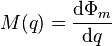
is known as memristance. This is comparable to the other three fundamental circuit elements:

  • Resistance: R(I)=\frac{\mathrm dV}{\mathrm dI}
  • Inductance: L(I) = \frac{\mathrm d\Phi_m}{\mathrm dI}
  • Capacitance: \frac{1}{C(q)}=\frac{\mathrm dV}{\mathrm dq}

Here q is electrical charge, I is electrical current, V is electrical potential and Φm is magnetic flux. The differential forms of these equations are used because we are comparing non-linear circuit elements; a linear memristor would be uninteresting, as explained below.

Applying Faraday’s law of electromagnetic induction and the chain rule to the equation defining the memristance, one obtains that the voltage V across a memristor is related to the current I by the instantaneous value of the memristance:

V(t) = M(q(t)) I(t) \,

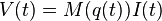
Thus at any given instant, a memristor behaves like an ordinary resistor. However, its “resistance” M(q) is a value which depends on the charge accumulated in the device. This differs from ordinary resistors where the resistance is determined by fixed physical properties and transistors where the resistance is controlled by either the voltage at or current through a gate electrode. A linear memristor (one for which M is constant) would thus be indistinguishable from an ordinary linear resistor (one for which R is constant), with M = R. Memristance can be said to depend on the history of the charge that has flowed through the device in the same way that the voltage of capacitors does.

The memristor is capable of “remembering” how much electrical charge most recently passed through it in one direction versus another. Thus, it can “remember” the state it was last in.

Fabrication :

Interest in the memristor revived in 2007 when an experimental solid-state version was reported by Stanley Williams of hewlett packard. A solid-state device could not be constructed until the unusual behavior of nanoscale materials made it possible. The device does not use magnetic flux as the theoretical memristor suggested, nor stores charge as a capacitor does, but instead achieves a resistance dependent on the history of current using a chemical mechanism.

The HP device is composed of a thin (5 nm) titanium dioxide film between two electrodes. Initially, there are two layers to the film, one of which has a slight depletion of oxygen atoms. The oxygen vacancies act as charge carriers, meaning that the depleted layer has a much lower resistance than the non-depleted layer. When an electric field is applied, the oxygen vacancies drift, changing the boundary between the high-resistance and low-resistance layers. Thus the resistance of the film as a whole is dependent on how much charge has been passed through it in a particular direction, which is reversible by changing the direction of current.

Samsung has a pending U.S. patent application for a memristor similar to that described by Williams.

Potential applications :

Williams’s solid-state memristors can be combined into devices called crossbar latches, which would replace transistors in future computers, taking up a much smaller area. They can also be fashioned into non-volatile solid-state memory, which would allow greater data density than hard drives with access times potentially similar to DRAM, replacing both components. HP prototyped a crossbar latch memory using the devices that can fit 100 gigabits in a square centimeter. For comparison, the highest-density flash memories at this time (2008) hold 16 gigabits. HP has reported that its version of the memristor is about one tenth the speed of DRAM.

The devices’ resistance would be read with alternating current so that they do not affect the stored value.