Komli

Showing posts with label SENSORS. Show all posts

Friday, April 17, 2009

Tactile Bump Sensors


button switch

These are mechanical touch sensors that are used to detect environment. They are used when you need to stop the bot after it touches some thing.

These are generally used with some whiskers like wire to detect from a far distance and mostly used in beam bots as they take very less power and give also very less power.I have seen some bots which use them for sensing the obstacles rather than using IR sensors or any other sensors as they are easier to use than ny other circuit designed sensors.

The other two types of switches are the magnetic reed switch and the membrane switch, which is much like a long button actuated switch.

Tuesday, March 10, 2009

Sensors to be used in Line follower

Hi evryone out there , I hope evryone is fyn and njyoing robotics , last 4 months had been a very tough job for me participating in ROBOCON , though we were not successful , I learnt a lot from this compt.
The first thing I would like to share is

Which Sensors to be used to detect black line??

I tried different circuits which even removes ambient light effect ( I will be posting the ckt oif it ) and IR sensors .Though I liked IR sensors the most , I was amazed to see the results when I used LDR sensors and White light . I used white light as my transmitter and LDR with a black tape covered as my reciever. The results were very good but the opnly problem was this is more sensitive to ambient light than IR sensors , but the change in ouput voltages were arnd 2 volts where as ir sensors always gave a change in output voltage of .89 .

If u want you can use LDR sensors with out a potmeter and opamp which I showed you in my ir sensor ckt.Give a try with ldr reciver ckt by replacing the transmitter and reciver with white led and LDR sensor

Wednesday, June 18, 2008

IR sensors From Scratch + Line follower


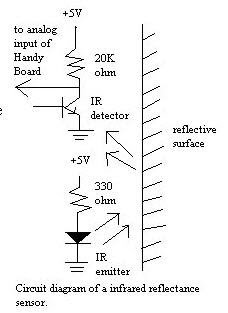
IR emitter and IR phototransistor
An infrared emitter is an LED made from gallium arsenide, which emits near-infrared energy at about 880nm.
The infrared phototransistor acts as a transistor with the base voltage determined by the amount of light hitting the transistor.
Hence it acts as a variable current source. Greater amount of IR light cause greater currents to flow through the collector-emitter leads.
As shown in the diagram below, the phototransistor is wired in a similar configuration to the voltage divider.
The variable current traveling through the resistor causes a voltage drop in the pull-up resistor.
This voltage is measured as the output of the device


IR reflectance sensors contain a matched infrared transmitter and infrared receiver pair.
These devices work by measuring the amount of light that is reflected into the receiver.
Because the receiver also responds to ambient light, the device works best when well shielded from abient light,
and when the distance between the sensor and the reflective surface is small(less than 5mm).
IR reflectance sensors are often used to detect white and black surfaces. White surfaces generally reflect well,
while black surfaces reflect poorly. One of such applications is the line follower of a robot.


Schematic Diagram for a Single Pair of Infrared Transmitter and Receiver


To get a good voltage swing , the value of R1 must be carefully chosen. If Rsensor = a when no light falls on it and Rsensor = b when light falls on it. The difference in the two potentials is:

Vcc * { a/(a+R1) - b/(b+R1) }
Relative voltage swing = Actual Voltage Swing / Vcc
= Vcc * { a/(a+R1) - b/(b+R1) } / Vcc
= a/(a+R1) - b/(b+R1)

The resistance of the sensor decreases when IR light falls on it. A good sensor will have near zero resistance
in presence of light and a very large resistance in absence of light. We have used this property of the sensor to form a potential divider. The potential at point ‘2’ is Rsensor / (Rsensor + R1). Again, a good sensor circuit should give maximum change in potential at point ‘2’ for no-light and bright-light conditions. This is especially important if you plan to use an ADC in place of the comparator

To get a good voltage swing , the value of R1 must be carefully chosen. If Rsensor = a when no light falls on it and Rsensor = b when light falls on it. The difference in the two potentials is:
Vcc * { a/(a+R1) - b/(b+R1) }

Relative voltage swing = Actual Voltage Swing / Vcc
= Vcc * { a/(a+R1) - b/(b+R1) } / Vcc
= a/(a+R1) - b/(b+R1)


If the emitter and detector (aka phototransistor) are not blocked, then the output on pin 2 of the 74LS14 will be high (apx. 5 Volts).
When they are blocked, then the output will be low (apx. 0 Volts). The 74LS14 is a Schmitt triggered hex inverter.
A Schmitt trigger is a signal conditioner. It ensures that above a threshold value, we will always get "clean" HIGH and LOW signals.
Not Blocked Case: Pin 2 High Current from Vcc flows through the detector. The current continues to flow through the base of Q2.
Current from Vcc also flows through R2, and Q2's Drain and Emitter to ground.
As a result of this current path, there will be no current flowing through Q1's base.
The signal at U1's pin 1 will be low, and so pin 2 will be high. Blocked Case: Pin 2 Low Current "stops" at the detector.
Q2's base is not turned on. The current is re-routed passing through R2 and into the base of Q1.
This allows current to flow from Q1's detector and exiting out Q1's emitter. Pin 1 is thus high and pin 2 will be low.
To detect a line to be followed, we are using two or more number of poto-reflectors.
Its output current that proportional to reflection rate of the floor is converted to voltage with a resister and tested it if the line is detected or not.
However the threshold voltage cannot be fixed to any level because optical current by ambent light is added to the output current.
Most photo-detecting modules are using modurated light to avoid interference by the ambient light.
The detected signal is filtered with a band pass filter and disused signals are filtered out.
Therefore only the modurated signal from the light emitter can be detected.
Of course the detector must not be saturated by ambient light, this is effective when the detector is working in linear region.


The line position is compeared to the center value to be tracked, the position error is processed with Proportional/Integral/Diffence filters
to generate steering command. The line folloing robot tracks the line in PID control that the most popular argolithm for servo control.
The proportional term is the commom process in the servo system. It is only a gain amplifire without time dependent process.
The differencial term is applied in order to improve the responce to disturbance, and it also compensate phase lag at the controled object.
The D term will be required in most case to stabilize tracking motion. The I term that boosts DC gain is applied in order to remove left offset error,
however, it often decrease servo stability due to its phase lag.
When any line sensing error has occured for a time due to getting out of line or end of line, the motors are stopped and
the microcontroller enters sleep state of zero power consumption.
Typical Examples of infrared Transmitter and Receiver installation


Tuesday, June 17, 2008

COLOUR SENSORS

All color sensors work on the basic principle that when light of some color falls on an object , if the object is of same color as of the led , then the object absorbs that color which means there is no reflection.

We would be making the ckt in the same way as we did for the IR led detector ckt , but we wuld be using LDR for our detection purpose , (IR cant be used as they catch only IR waves) , and in place of the IR transmitter we wuld be using three leds of red, blue and green.

WORKING:
Light up each of the leds one at a time , ie red , then blue n green , if the obstacles are of red blue and green colour then you wuld be getting different outputs ( REMEMBER VIBGYOR) .

With micrcontrollers , lit up the red led if there is reflection take the ADC reading
do the same for other leds and take thier ADC reading , we will know which colour its detecting.
One sensor wuld be lit up always .


Use a potentiometer with each of the LEDs to get a better reading , as there wuld be slight color difference .The circuit will be the same as for the ir sensor which i have explained in my previous post , with litlle changes .Hope u njyd it

Saturday, May 17, 2008

SENSORS WITH TSOP CKT


This is a simple yet effective IR proximity sensor built around the TSOP 1738 module. The TSOP module is commonly found at the receiving end of an IR remote control system; e.g., in TVs, CD players etc. These modules require the incoming data to be modulated at a particular frequency and would ignore any other IR signals. It is also immune to ambient IR light, so one can easily use these sensors outdoors or under heavily lit conditions.
Such modules are available for different carrier frequencies from 32 kHz to 42 kHz.They cost some thing around 20Rs.
In this particular proximity sensor, we will be generating a constant stream of square wave signal using IC555 centered at 38 kHz and would use it to drive an IR led. So whenever this signal bounces off the obstacles, the receiver would detect it and change its output. Since the TSOP 1738 module works in the active-low configuration, its output would normally remain high and would go low when it detects the signal (the obstacle).

In the reciving part instead of using IC555 u can use the time from u r muc.

Wednesday, April 9, 2008

Simple IR LED CKT


We will be using over here an irled pair and a comparator .When the reciver led recivers the signal the voltage acros it would be going high.This we would be putting across the + ve of comparator, n to the -ve of comparator we wuld be using a potentiometer . When the reciver does not recive any signal the voltage across the pot wuld be set up in such a way tat voltage across it is high so the output wuld be zero volts.
Wehen the reciver recieves the signal the voltage at +ve of comparator would be more than that of -ve end so the out put wuld be high.The pot is used to adjust from how much distance the reciever is able to detect .

THE LED WHICH U C IN THE CKT FROM LEFT ARE 1ST ONES A IRLED TRANSMITTER ,2ND ONE IS A IR TRANSMITTER AND THE 3RD ONE IS A NORMAL LED WHICH WILL GLOW MOSTLY RED IS USED
From my xperince i can tell tat this will give u arnd 5 cm obstacle detection , voltage drop across reciver for me was .47V when it didnt sense the obstacle , when it did sense it was giving arnd.58v so now the voltage at the -ve pin shld be brought to this voltage by rotating the pot .
The leb which u c at the ouput will glow when it detects an obstacle.

The output which u get from the comparator will be fed to logic gates r micrcontrollers .

SENSORS

This is the most important part of an autonoums bots , without this der cant be an autonoums bot build. There are different types of sensors used varying with work to be done with the bot.

1)Light sensors
This sensors are used to measure the intensity of light.Mostly commonly used under this are LDR(light dependent resistors) , TSOP1738,IRLED pair,Photodiode,Phototransistor.
USES :
Th
ey can be used as obstacle avoidance, in line follower to differentiate btw black and white.


LDR:

Its
a resistor whose value decreases with intensity of light, more the intensity of light lesser will be the resistence and vice versa , which means when this sensor is in dark place there is less resistence.Now the question will be how can we use it as sensor for our bot we use LEDs(red mostly) in combination with LDR,.


I L PUT UP THE CKT OF IT IN MY OTHER POST.
http://www.technologystudent.com/elec1/ldr1.htm (FOR MORE HELP)

2)IR LED:
Its
basically a pair of diodes one is the reciever and the other a transmitter(dark blue in colour) both modulated to same frequency .The transmitter works in forward bias condition and the reciever in reverse bias condition.It has two terminals the longer one is the + ve one n other -ve .

How does it work:
The
transmitter sends a light at partiular freq though u cannot c it , the receiver detects it when it bounces back from some obstacle.
THE CKT WULD BE PUT IN OTHER POST.
This sensor is mostly used by students for various competiotns.


3)TSOP 1738:

This is mostly used when we want our sensors to work in more ambient lite , sunlite i can say for.
This thing is found in TV remote controller.

THESE SENSORS TAT I HAVE TOLD ARE ONLY LIGHT SENSORS,
Apart from these the sensors tat are there are
accelometers :Used to detect motion, vibration, ngle with respect to gravity
Colour sensors:Used to detect diff colours
Sonar Sensors:Determines obstacle from a distance
Bump switch:touches the object and gives the signal

I will discuss about these sensors in more detail in later posts .