In three wheels differential drive configuration two wheels are connected to motors.
Third wheel is caster or omni directional wheel which allows motion in any direction.
Three wheeled configuration is often used in smaller size robots.
It offers two advantages:
1. All the wheels gets good contact
2. Problem of skidding while turning is avoided.
3. Robot can take turn by stopping one wheel and moving other wheel
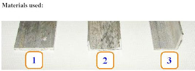
MATERIALS USED

1. Flat Aluminum stripe: Width: 1 inch, Length 1 feet, thickness approx 1.5 mm or
above
2. Aluminum ‘C’ channel: Width: 1 inch, Length 1 feet, thickness approx 1mm or
above
3. Aluminum ‘L’ angle: Width: ¾ * ¾ inch, Length 5 feet, thickness approx 1mm or
above
FABRICATION OF MACHINES CHASSIS
Cut Aluminum ‘L’ angle of 14 cm length. ( and Aluminum ‘C’ channel of
16 cm length. (
Now fix Aluminum ‘L’ angle or ‘C’ channel firmly in the bench wise . Mark
Aluminum channel using tri square (. (this will make sure that cutting
guidelines at right angled to the angle / channel.)

Cut Aluminum angle / channel with hexa blade.


Now arrange the 14 cm ‘L’ angle and 16 cm ‘C’ channel in ‘T’ configuration as shown in
fig. 1.17. Drill holes with 3mm of 1/8 drill bit ( using drill machine on the
intersection of channel and angle.
Use 3mm nut and bolt: flat head, 10mm in length along with Spring washer
for 3mm or 1/8 inch nut and bolts for join the ‘L’ angle and ‘C’ channel.
Spring washer will prevent loosing of nuts and bolts in vibrations.
Always use spring washer between the nuts and bolts.
Be very careful while holding bolt with Pliers and tighten nut with screwdriver. If
screwdriver slips it can hurt other hand

As shown in fig above DC geared motors gearbox’s diameter is slightly bigger than
diameter of motor. For better motor mounting gearbox and motor should have same
diameter. For increasing motor diameter of the motor foam tape is used(the thing in yellow).
Place the motor on the ‘L’ angle and tightly wrap tape around it. Do the same procedure
of the other motor. It is very important that motors back side touches ‘C’ channel. This
will be explained in fig later on.
Photo showing chassis after motor mounting is shown above .
Now we will mount caster wheel at the front end of the chassis. First place caster wheel
on the Aluminum ‘C’ channel at the front side. Mark three holes on the ‘C’
channel. Drill holes with 3mm of 1/8 drill bit ( using drill machine. Mount 3
25 mm studs (fig below) using 3mm nut flat head nut (fig below). Mount caster wheel
on the studs using counter sink nuts (fig below).

Take old piece of tire tube (fig 1.24) and cut approximately 11mm band. Stretch the
rubber band to remove its stiffness. Now mount two such bands on the motor. This will
make motor mounting firm.

Mount wheels (fig 1.13) on the two motor shafts.

Now u can mount the batteries on the chassis by making a small box either of aluminium r the some other material and fix it on to the chassis
NEXT TAKE A TEN WIRE STRIP AND GIVE THE CONNECTIONS TO THE DPDT SWITCH AS TOLD IN EARLIER POST .
THERE IT IS FINALLY U R FIRST MANUAL CONTROL BOT
FOR DIFFERENT EVENTS U CAN KEEP CHANGING THE CHASSIS AS THIS WAS BUILT KEEPING IN MIND OF LOW WEIGHT WE DID THIS THING U CAN ALSO WOOD (I PREFER XAM PAD AS MY CHASSIS) AS U R CHASSIS ALSO REST OF IT I WILL TELL U IN MY NEXT POST.

No comments:
Post a Comment