All these books have been take from the site allfree.freemaniz site .I have read most of the books and i will give my opinion on these so it will be useful to you.
First book which all beginners shuld read for robotics .
Tata mcgrah hills robot builder's bonanza.
download from here
Robotics project outlined by pic microcontroller infact a tutuorial on pic
download from here
Architecture on microcontroller by ayala .A complete text book of AYALAs muc.
download from here
Matlab programming for Image processing
Download from here
Robot mechanical building tips .Very gud book if u really want to make one robus mechanical bot with perfection.
download it from here
Autonomous mobile robotics .Amazing book if u want to make one great autonoums navigation bot.It tells evrything from makng a biped(a litle bit) , a very gud autonoums bot.
download from here
Making a pac -man robot very fun makng, it indeed wil give u a xperince in how some problem statements are solved.
download from here
And last but not the least my site , i will be updating it very frequently so tat when the next year starts I mean next sem , as robotic competetions wuld be startng u will find lot more help from here keep checking .Till then thnx from all u guys.
My next post will be on logic gates and K map(karnuagh map) , to make autonoums bots without microcontroller.
Friday, April 18, 2008
Friday, April 11, 2008
LINE FOLLOWER
This will be the first start to our autonoums bots , this is the most famous competetion held in most of the colleges , n i have seen people asking at lot of places asking for this now i will try to make this post a one stop to make a line follower , if u have understood the previous 4 things ,
firstly the motor driver , then op amp , sensors, which i have told in my last posts n the the most important part either using logic gates r else using micro controllers tats programming it .
I will be tellng u both the ways of doing it tats using logic gates and also using muc(i will be gvng only the logic part ).

This is how it basically luks like
I will xplain making of a line follower using one sensor till an array of sensor(ie 7 sensors).
BASIC PRINCIPLE:
White colour reflects light and black colour absorbs .
So when the sensor is on the white line the output will be high and when on black it will be low.

WE ASSUME WE ARE FOLLOWING A BLACK LINE ON WHITE BACK GROUND.
LFR USING A SINGLE SENSOR
Lets assume tat sensor is placed on center ie the sensor correctly places above the line , then there is no way tat it can follow a line bcoz it cant diff btw curves tilted towards left n right.
so wat we do is place the bot in such a way tat when the sensor cums to the right side of the line .
conditions:
1)when the sensor is not on the main line move fwd.
2)when the line is turning towards left the sensor detects the line so now take a left turn
3)when the line is turning towards rite u r sensor cant detect the line and it keeps moving forward as it satisfies condition number 1
RESULT:We cant use this thing.
LFR USING TWO SENSORS:
We place our sensor on either side of the line .
conditions:
When the line is straight and the two sensors are on either side of the line, move forward
when there is a right bend in the line the right sensor detects it ,now as ur bot shuld take turn, the rite motor shld stop and the left motor shuld move.
when there is a left bend in the line the left sensor detects it ,now as ur bot shuld take left turn, the left motor shld stop and the rite motor shuld move.


The pic shows the left curves and the right curves, the blue ones are u r sensors, the left pic shows the left sensor about to detect the line and the rite pic shows the right sensor about to detect the line.For the ckt directly connect the output of sensors to the the inputs of l293d n tat s it but use 30 rpm motors for it hope u got it .
But the problem with this is it will always move in zig zag manner so wastage of time.
I will give the ckt diagram of this after i explain about Logic gates .
And remember this is only with two sensors , i will explain till we can use 7 sensors so keep checking.
Wednesday, April 9, 2008
Simple IR LED CKT

We will be using over here an irled pair and a comparator .When the reciver led recivers the signal the voltage acros it would be going high.This we would be putting across the + ve of comparator, n to the -ve of comparator we wuld be using a potentiometer . When the reciver does not recive any signal the voltage across the pot wuld be set up in such a way tat voltage across it is high so the output wuld be zero volts.
Wehen the reciver recieves the signal the voltage at +ve of comparator would be more than that of -ve end so the out put wuld be high.The pot is used to adjust from how much distance the reciever is able to detect .
THE LED WHICH U C IN THE CKT FROM LEFT ARE 1ST ONES A IRLED TRANSMITTER ,2ND ONE IS A IR TRANSMITTER AND THE 3RD ONE IS A NORMAL LED WHICH WILL GLOW MOSTLY RED IS USED
From my xperince i can tell tat this will give u arnd 5 cm obstacle detection , voltage drop across reciver for me was .47V when it didnt sense the obstacle , when it did sense it was giving arnd.58v so now the voltage at the -ve pin shld be brought to this voltage by rotating the pot .
The leb which u c at the ouput will glow when it detects an obstacle.
The output which u get from the comparator will be fed to logic gates r micrcontrollers .
SENSORS
This is the most important part of an autonoums bots , without this der cant be an autonoums bot build. There are different types of sensors used varying with work to be done with the bot.
1)Light sensors
This sensors are used to measure the intensity of light.Mostly commonly used under this are LDR(light dependent resistors) , TSOP1738,IRLED pair,Photodiode,Phototransistor.
USES :
They can be used as obstacle avoidance, in line follower to differentiate btw black and white.
LDR:
Its a resistor whose value decreases with intensity of light, more the intensity of light lesser will be the resistence and vice versa , which means when this sensor is in dark place there is less resistence.Now the question will be how can we use it as sensor for our bot we use LEDs(red mostly) in combination with LDR,.
I L PUT UP THE CKT OF IT IN MY OTHER POST.
http://www.technologystudent.com/elec1/ldr1.htm (FOR MORE HELP)
2)IR LED:
Its basically a pair of diodes one is the reciever and the other a transmitter(dark blue in colour) both modulated to same frequency .The transmitter works in forward bias condition and the reciever in reverse bias condition.It has two terminals the longer one is the + ve one n other -ve .
 How does it work:
The transmitter sends a light at partiular freq though u cannot c it , the receiver detects it when it bounces back from some obstacle.
THE CKT WULD BE PUT IN OTHER POST.
This sensor is mostly used by students for various competiotns.
3)TSOP 1738:
This is mostly used when we want our sensors to work in more ambient lite , sunlite i can say for.
This thing is found in TV remote controller.
THESE SENSORS TAT I HAVE TOLD ARE ONLY LIGHT SENSORS,
Apart from these the sensors tat are there are
accelometers :Used to detect motion, vibration, ngle with respect to gravity
Colour sensors:Used to detect diff colours
Sonar Sensors:Determines obstacle from a distance
Bump switch:touches the object and gives the signal
I will discuss about these sensors in more detail in later posts .
1)Light sensors
This sensors are used to measure the intensity of light.Mostly commonly used under this are LDR(light dependent resistors) , TSOP1738,IRLED pair,Photodiode,Phototransistor.
USES :
They can be used as obstacle avoidance, in line follower to differentiate btw black and white.
LDR:
Its a resistor whose value decreases with intensity of light, more the intensity of light lesser will be the resistence and vice versa , which means when this sensor is in dark place there is less resistence.Now the question will be how can we use it as sensor for our bot we use LEDs(red mostly) in combination with LDR,.

I L PUT UP THE CKT OF IT IN MY OTHER POST.
http://www.technologystudent.com/elec1/ldr1.htm (FOR MORE HELP)
2)IR LED:
Its basically a pair of diodes one is the reciever and the other a transmitter(dark blue in colour) both modulated to same frequency .The transmitter works in forward bias condition and the reciever in reverse bias condition.It has two terminals the longer one is the + ve one n other -ve .
How does it work:The transmitter sends a light at partiular freq though u cannot c it , the receiver detects it when it bounces back from some obstacle.
THE CKT WULD BE PUT IN OTHER POST.
This sensor is mostly used by students for various competiotns.
3)TSOP 1738:
This is mostly used when we want our sensors to work in more ambient lite , sunlite i can say for.
This thing is found in TV remote controller.
THESE SENSORS TAT I HAVE TOLD ARE ONLY LIGHT SENSORS,
Apart from these the sensors tat are there are
accelometers :Used to detect motion, vibration, ngle with respect to gravity
Colour sensors:Used to detect diff colours
Sonar Sensors:Determines obstacle from a distance
Bump switch:touches the object and gives the signal
I will discuss about these sensors in more detail in later posts .
Tuesday, April 8, 2008
OPAMPS n COMPARATORS
As the name implies it is an operational amplifier. It performsmathematical operations like addition,subtraction,log,antilog etc.. Themain reason for OPAMPS used over transistors is that transistor can onlyamplify AC while OPAMPS can amplify AC and DC. You can get good amplifier gain in OPAMPS. The most commonly used OPAMPS are 741 ,LM 324, LM 358N(both of them can also be used as comparator).
Comparator is also the same but with a diff being tat its digital so u have to two states high(5V) and low(0V).
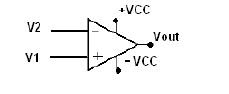 FIGURE 1.
Above figure shows the general ckt diagram of a comparator .If V1>V2 then Vout=+Vcc and if V1 if V1 is less than V2 then Vout is minus Vcc

Lm 324 has 4 such comparator(shown in figure1) them also known as Quad opamp.
LM 358N has 2 comaprator also known as bi opamp.
EXPERIMENTAL PART:
U can use two potentiometers(of 10 K prefarably) and put them across pin2 and pin 3 , and put an led in series with a resistance at pin 1 , when the voltage drop in pot 1 connected across pin 2 is low , u can c the led glow.
Voltage regulator
As the name suggets it regulates voltage tat is it can provide either constant voltage r variable voltage(DC only)
Fixed Voltage regulators (78xx,79xx) [7805 being the most popularly used ]
Variable Voltage regulator (LM 317)
Fixed Voltage regulators
This include 78xx voltage regulators. The most commonly used ones are 7805 and 7812. 7805 gives fixed 5V DC voltage if input voltage is in (7.5V,20V).If the voltage is below 7.5 V u mite get the output voltage as 4.6-4.8 V.
This is how 7805 luks like:

IN is the 1st pin where u give the + of power supply OUT is where u get 5 V o/p + and COM is where u give the negative terminal of the power supply , n take it again as the - ve of 5 v o/p.
CHECK BELOW FOR THE CKT DIAGRAM

Its not really not necessary to use those capacitors , I never used them .
It will be the same for - ve voltage regulators , I will talk abt variable voltage regulators in my next post
Autonoums Robotics part 1
Before starting of with this get well educated with some electronic components though much detail is not needed , u can do most of the work using data sheet of the electronic components.
1)voltage regulator
2)op amp and comparator
3)motor driver
4)microcontrollers
resistors ,capacitors , transistors wuld also come along with this thing
When u make an autonoums robots the basic thing needed wuld be
1)Brain (microcontroller,logic gates)
2)Eyes(Sensors)
3)Hands and Legs(Motors, Wheels)
so u r sensors take care of the surroundings, send the feed back to microcontrollers r logic gates
n then the output to the motors to do the desired things
so i will be covering up all this thing in parallel both electronic parts and the sensors , microcontrollers, then giving the motion to wheels in the order as told above.
Hope u all will like it .
Monday, April 7, 2008
MOTOR DRIVER CKT
All the motors (dc) run at 12 v supply but the output u get from u r logic gate ,microcontrollers opamp is 5v which cannot make motor run.Motor driver is the most essential part of any autonoums bots , generally people use L293D for running dc motors , u can run 2 dc motors with this IC though it can take a maximum current of 600 mA per channel which is more than enough for us to drive the motors.

The ckt diagram of it goes like this

M1 M2 are the motors(dc motors) ,M1A ,M1B are the controls of motor M1 and M2A ,M2B are the controls of motor M2.M1A ,M1B,M2A,M2B are the inputs tat u get from logic gates r the muc , opamps, to the recieving end of reciever in wireless module
here is the tabe describing the function of the pins
if pin1 is high if pin 9 is high
M1A M1B FUNCTION M2A M2B Function
H L cloclwise H L clockwise
L H anitclockwise L H anticlockwise
L L fast stop L L fast stop
-----------------------------------------------------------------------------------
make pin 1 low slowstop make pin 9 low slowstop
Pin 1 n Pin 9 make each of the channels high (there r two channels) n the pin 8 voltage can go upto 24v
U get this Ic for a cost of Rs 75 .
hope i have explained evrything in detail
Making a wireless remote
Get rid of those long wires tat tangle all the time , there are different ways of making a wireless module using ready made rc cars n putting relays near the out put u can drive u r 12v motors ,then theres IR remote control though not tat much reliable n then theres dtmf tats thr cell phone n gprs communication, n the most simplest of them using rf modules , in consideration with all the above ways rf module is the most easiest n most cheapes (RS 550) nothing more .
 This shows the transmitter(TX) n reciever (RX) which u get in electronic shops. TX 01 ASK MODULE and RX 02 ASK MODULE are used here n shown above .
our basic idea goes like this
 The two ics HT12E n HT12D r the encoder n decoders of 4 adress bit this is used as we need to drive two motors ,where each motor takes in 2 adress bit (1 for forward rotation other for reverse ) so in all we need four adress bits
if u want to control more number of motors u need to change encoder and decoders. At place of those switches u can either use push buttons r dpdt switches (ckt of dpdt switch is show here click here)
now near the recieving end u use a motor driver bcoz u get 5V as output but motors need 12v to drive them(i have explained this here in much detail ) The ckts are shown over for transmitter and recieving end


D1 D2 D3 D4 will go to the input of motor driver (check the motor driver ckt) n from motor driver to the motors .
This ckt has been tested by me n was giving a ver good range also.The best place to buy is aplusindia.com it sells it for very cheap and u dnt get much cheaper than at this place.
Hope i have made it very clear .
Subscribe to:
Posts (Atom)